This is an old revision of the document!
−Table of Contents
Work Journal
Decided to try and keep this daily work journal so I don't lose track of the work.
Sat 02/02/2019 - Robotics Day (retrospect)
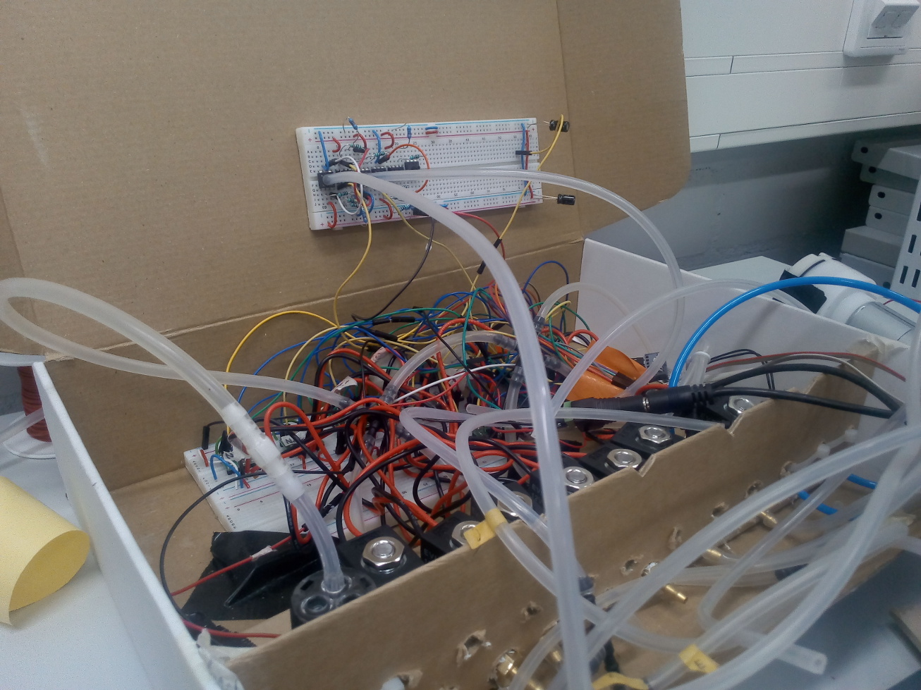
This was an attempt to showcase Hitodama after ~3 days of work with the help of Joaquin. Joaquin was able to arrange the valves wiring in a tidy box. It looks great (for a breadboard setup), but I'm worried on whether it will scale up when I need more valves (soon). I got good feedback during the show, as most people haven't seen this type of robot before (some even named it as their favorite of the show!), and the kids really enjoyed playing with the pumps, but it was also not stable or presentable enough to get the full experience. Faults:
- Didn't have time to setup the pressure senors, or tune the inflation/deflation speeds so was basically limited to quick inflation and deflation - this movement is not natural and doesn't really show the potential of soft robotics.
- Was only able to setup the two arms and 2/3 neck actuators.
- The valves were all leaking - I didn't know that NPT connectors are meant to be wrapped by PTFE tape (This is the first time I use these valves on display, previous 'generaton' had the smaller valves).
- In the last minutes before the show I could get the arms kind of working, but they both broke during the show - being hung down when deflated hurt he wires. During the show one arm sensor stopped responding completely and the other was unstable.
Mon 04/02/2019 - (retrospect)
I spent this day unpacking the robot and cleaning the desk at the Mechatronics workshop.
Tue 05/02/2019 - (retrospect)
Checked the left arm which broke completely at the Robotics day. The problem was at the “shoulder” area, the connection between the conductive fabric threads and my soldering to the ribbon cable. One cable got disconnected. Fixing the conductive threads is difficult because they tear apart and become inaccesisble, I had to poke a wire with some solder into the silicone and heat it up to try and connect with the fiber, eventually I could do it and was able to create a bridge to the ribbon cable. It remained relatively clean because the “shoulder” area has more space to playing around with, but it's still not super stable. TODO: Needs an isolation solution. Perhaps with the help of Joaquin.
Wed 06/02/2019 - (retrospect)
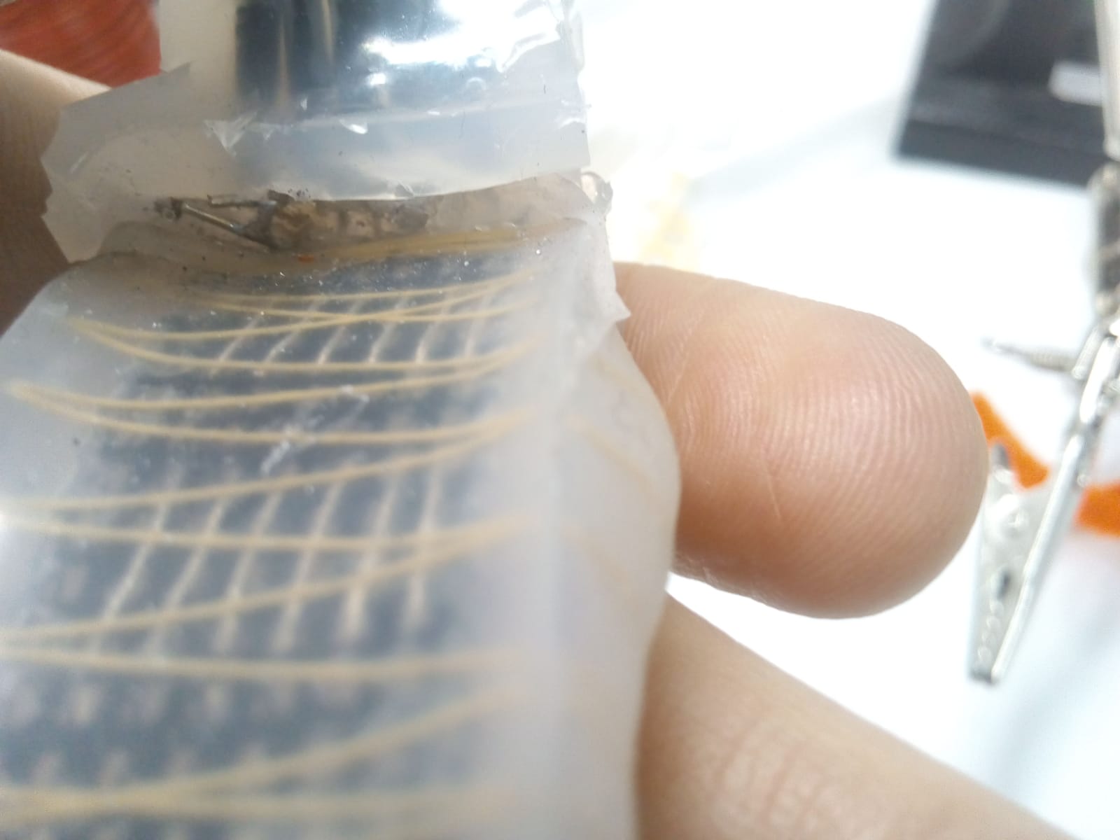
Just when I thought the arms are fine now, the other arm (right one) started having issues and these ones were worse, because there was a disconnection in the sensor area. At that point I decided to not use conductive threads again for this task, even though I'm still not sure if the problem is because of my bad soldering. It might be that having the threads submerge in silicone damages their durability. Note that I'm using the rare and best kind of fibers by Mitsufuji, graciously gifted to me by the woman at Kobakant Berlin. There was no choice, I had to do surgery and cut open the sensor. While examining, literally all of the conductive threads tore apart. It took many hours, but eventually I could do the poking solution with all of the pins, but it was probably a mistake to bridge from the button of the sensor and not from above, because now the hand won't close up:
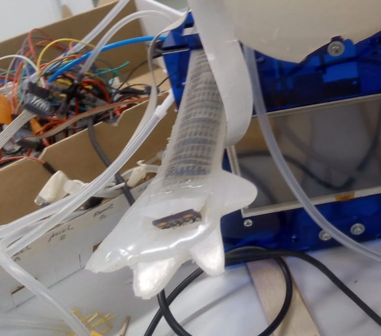
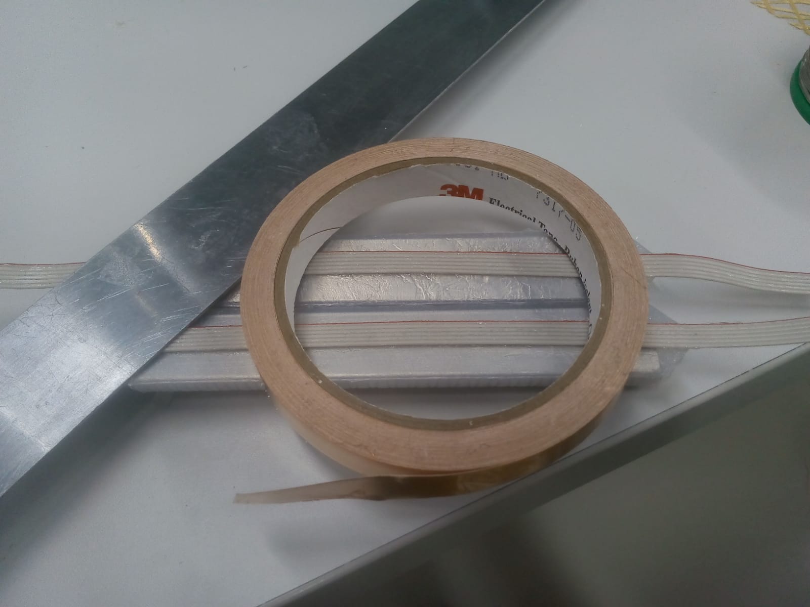
However surprisingly pressing the palm still works pretty well, so at least it's a temporary solution. Meanwhile I am continuing the production of two new arms, this time trying to avoid the threads all-together by gluing the ribbon cable directly, basically having it as both the conductive and the fabric actuation restraining layer:
The thickness of the cable is 1mm so there shouldn't be an issue with the skin casting, hopefully. As for the temporary arm, I believe I can fix it later on by re-soldering the bridges to the sensor from the top instead from from the bottom. I can't really make the new arms yet anyway, my Ecoflex is too old. I ordered a new pack from Kaupo.
Thu 07/02/2019 - (retrospect)
I moved on from the arms to debugging and developing the air-flow to the actuators. This is a new setup compared to the one I had in Japan, and not thoroughly tested. The first issue was leakage. All of the valves were leaking. I performed some tests and read about the NPT connections, finally realizing that these connections are designed to be sealed by PTFE tape (Joaquin was actually suggesting this earlier, but we didn't know it's a must, well it is). I moved on to testing the pressure sensors. I thought these are the same ones that I had in Japan, but I was wrong. They are actually the MPS20N0040D or a very similar clone. Turns out the pinout is different and that these sensors require an Operational amplifier. I spend the day trying to understand what that even mean and ordered some from Matti.
Fri 08/02/2019 - (retrospect)
Went to Motonet and IKH, got PTFE tape(s) and some more NPT connectors for testing. TODO: Need to buy at Etra more of the larger silicone tube for the large NPT connector, and converters between the large and the small. Also buy even smaller ones for the connection to the actuator. I put the PTFE on the valves and it did stop the leak, but last time I tried there was still something coming out, I think it might be other valves that I forget that are connected and I didn't seal yet TODO: Check that. Janne had some LM358 Op-Amps so I went and tried that with the pressure sensors, couldn't get it to work. I got a constant output coming out of the Op-Amp. TODO: Now I found this page that shows how they connect resistors to the LM358, could be that is what was missing.* But anyway, eventually I analyzed the signal with the Oscilloscope and then with the Arduino and I found one pin that was changing the voltage in response to pressure. It might be that that's all I need. I implemented a pressure reporting component to the software but it wasn't working yet how I wanted it to. TODO: Report the pressure using 2 bytes instead of 1!
Mon 11/02/2019
Went and sealed with PTFE all of the valve connectors. Wasn't very good at it, and had to redo some of the wrappings. Eventually managed to have leak-proof arm actuation, but after about one hour it started leaking again. Did some tests and ended up with the conclusion that one valve died. It wasn't 'normally-closed' anymore and it kept transmitting air. I wonder if using PWM on the valve is abusing it? Anyway, I replaced the valve with another one and marked it as “Broken”. Then moved on to experimenting with the pressure sensors. The software component is fine, but I am starting to reach the conclusion that I do need the Op-Amp. The range I get is very small and seems unstable, making it very hard to determine the minimum and maximum pressure on the software. Even if I calibrate the pressure as a base pressure value every run, it can still be unpredictable. I need to try the resistor setup with the LM358.
Tue 12/02/2019
I spent the day learning about electronic circuits and Op-Amps, but still don't fully grasp all of the concepts. At the end of the day I was able to get meaningful, but not amplified output from the LM358 chip. It seems that the sensors I have are not exactly the same as the MPS20N0040D-D mentioned in all of the documentation, which causes inconsistent results. This is either way not a very scalable solution, requiring an Op-Amp (probably dual, not to mention filters etc) setup for each pressure sensor. I could probably use this now for testing, but shouldn't spend more than this week to get it stabilized. I think I should just find a way to order the pressure sensors that I had in Japan. For example:Through here?
Thu 14/02/2019
After the last couple of days I can finally say that I have an adequate understanding of Op-Amps. One website that enlightened me after getting lost in the mathematical jargon was this one. I was able to amplify the Chinese sensor sufficiently to get a good range of values and it also seems more stable now that I'm wiring all of the pins on the sensor into the differential amp.
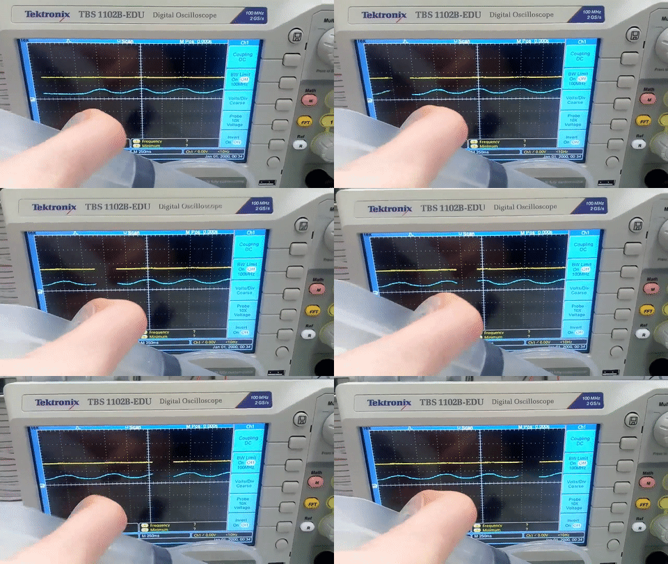
After manual testing I believe that I can work with this sensor, but it seems I should still to a little bit of averaging on the software side because opening and closing valves seems to cause sudden and very transient drops in voltage. The final test would be whether I can run my “Pressure oscillation” code (inflating up and down) in a stable manner. If that works, I will document my setup in the Wiki and continue hooking up more pressure sensors. TODO: I need more Op-Amps and resistors though. Simultaneously I've still been searching for other sensors that I can buy, or a vendor that sells that Metrodyne sensors I used in Japan. Eventually I contacted the company itself in Taiwan and got a quick positive reply asking me for the quantity and application. I responded but haven't heard from them back so far.
Mon 18/02/2019
Work in the recent days is divided into two categories:
Pressure Sensors
In the weekend I ran more tests on the amplified, cheap pressure sensors. My goal was to have “Oscillations” working correctly. I ended up putting a bunch of optimizations to the pressure calculator. Primarily:
- Averaging the pressure calculation - currently averaging over a 100 read window.
- Accounting for fluctuations - I have noticed that when closing the valves after deflating or inflating, there is a sudden fluctuation. For example, inflating until I reach 200, then closing the valves, would result in a quick drop to 190. The opposite effect would happen when deflating. To account for that, I am now 'overshooting' the inflation/deflation, inflating for example up to 210 and then letting it drop back to 200.
I have also documented the setup and gathered the material in here.
Now I have started to arrange the pressure sensors on a new breadboard, utilizing the LM358s with 2 sensors per chip. But I ran out of the resistors to use, so I have ordered some from PartCo and they should arrive soon.
WPE
The interaction of Hitodama is Web-Powered and runs on Raspberry Pi.
About a year ago I found out about the project WPE - "Webkit Platform for Embedded". At that time it was fairly immature, but I did manage to generate a 'buildroot' image that runs WPE, and even my Rust controller. Now, coming back to it, a few things have changed and I began researching again about the best way to run WPE. After a lot of confusions and attempts, I ended up on the #webkit IRC channel on FreeNode asking for help, and was super lucky to get advised by one of the creators of WPE. I have linked my chat with him in the page: webkit-wpe_.log.txt
Now I am in the process of building another buildroot with all of the latest stuff, it's pretty exciting!
Wed 20/02/2019
Pressure Sensors
Yesterday I started arranging the pressure sensors on the breadboard and connecting them to the main circuit. It looks like this:
Overall it seems nice, but I am worried about scaling. Especially with the valves. So far I have connected two of the neck muscles.
Valve troubles
I am spending time figuring out the valves and their quirkiness. I am using PWM outout to try and open the valve only partially. It seemed to work with the first actuator (Neck Right), but then it didn't work with the left muscle. It seemed as if closing the entry valve disabled my ability to run PWM on the release valve. I have no idea why, but I managed to solve this by changing the IN2 pin of the entry valve. Here is how the configuration was when it didn't work:
    Chamber("LeftNeck",
            new Valve(2,4,5,25),
            new Valve(2,3,5,25),
            A16,
            120,
            300
    )
And here is how it does work:
    Chamber("LeftNeck",
            new Valve(2,26,5,25),
            new Valve(2,3,5,25),
            A16,
            120,
            300
    ),
I updated the Teensy 3.6 Hitodama pin assigns Google Doc that Joaquin made.
The second thing I am realizing is the non-linearity of PWM (especially on the solenoids, but also on motors). Each valve has its own configuration of a PWM value that is low enough for it not to open completely. Looks like I have to provide PWM values for each actuator separately.
However, it seems that there is room to play with the way PWM is sent. The control board in here references this code, where it seems like they are modifying the Arduino's registers to change the form of the PWM! I need to learn more about this, but there is also a guide for Teensy in here. TODO: Learn about the concept of Duty Cycle, which is also used to describe the operation of biological muscles
With the advice of Otso I tried to implement a mini-envelope for sending the PWM wave. Basically I opened the valve entirely for some cycles and only then closed it partially. This was supposed to get over the “friction” for opening a solenoid partially. However it didn't really do anything, there should be a smarter solution. Anyway the code for this version of valve is here. What I did end up doing was increase the resolution of the PWM, to get a more stable value. I used 10 bits:
analogWriteResolution(10);
I might be able to live with that.

